Chaotica: Intermediate Linear Tiles
Credits
A huge thanks to the fractal community is in order.
If I have seen further than others, it is by standing upon the shoulders of giants. - Isaac Newton
Introduction
In this tutorial, we’re going to create a more advanced linear tile and then explore some possible camera modifications to it. If you haven’t seen the rest of my tutorials, make sure you check them out. You can find them at the top right of the page, or click HERE
Planning Phase
First, you decide what you want to tile. Usually my personal method is to start with a broad idea of what I want to accomplish and then get more detailed as time goes on. To start with, let’s create a tile that’s a bit different than a standard 1x1. Lets try a 1x2 tile instead.
It’s been asked for me to provide this information, so here it is. My development usually occurs at 1280x720 resolution so even the free version of Chaotica can load the file.
Creating a Tile
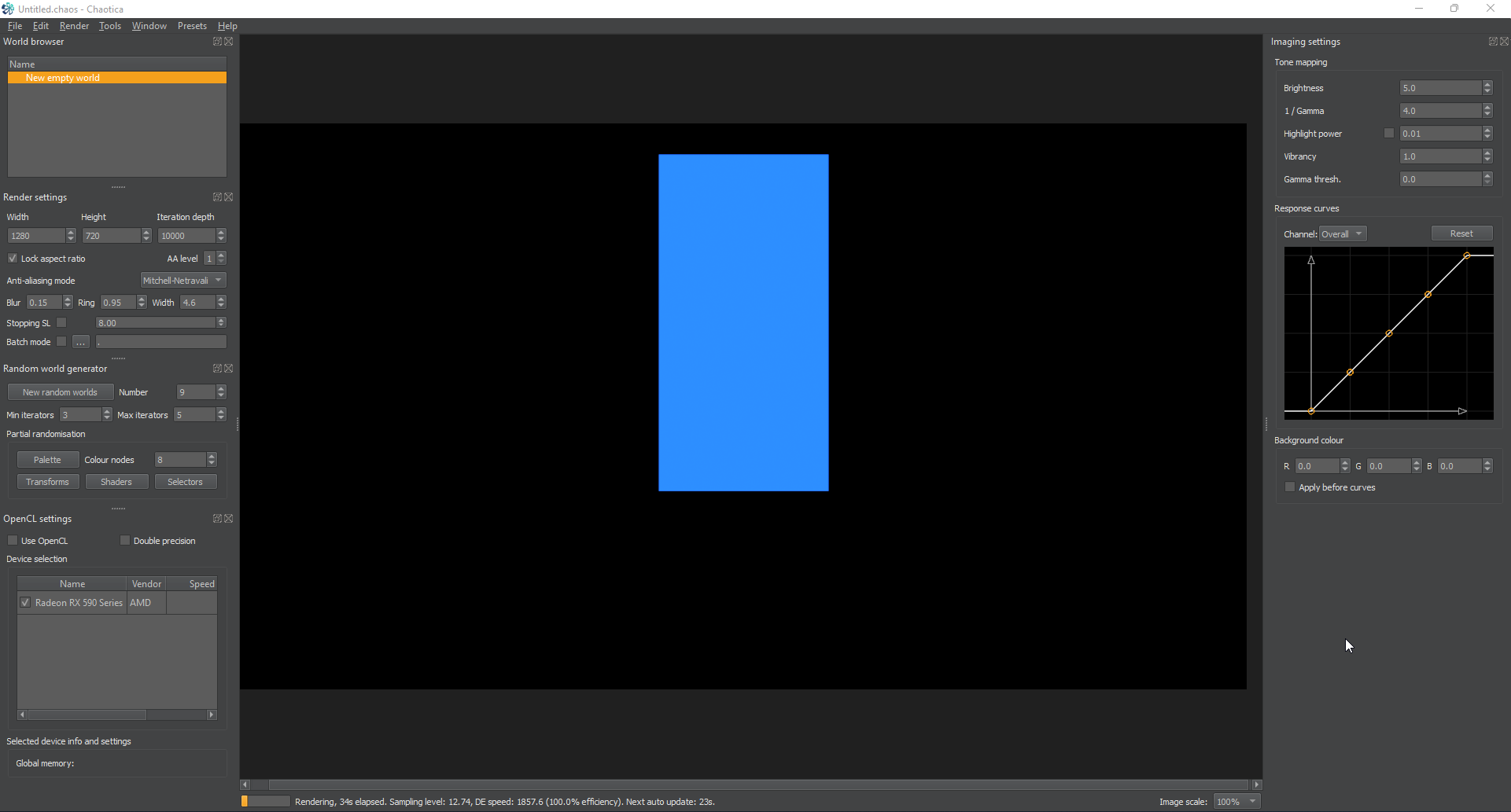
First, I’m going to set up the base structure. Just to keep things organized, we will create two squares and stack them on top of each other and then once we have the right size setup, we can start modifying them and filling them out with interesting constructions. So I can see everything, I’m going to change the camera sensor width to something like 6. That way everything is in view. Feel free to adjust as needed.
Opening Blurs
First, I’m going to open Chaotica and create a new world. Next I’m going to create two iterators. I’ll set the first up with square as the transform and the second the same as the first, but with a post-affine of y=-1 in order to move the second one up by 1 unit.
Bottom Square
Now I’m going to take the bottom square and do some modification. I think it would look awesome if I cropped out the middle and then put another iterator in there with maybe a loonie or possibly a hemisphere. So let’s do that.
First, I’m going to take the first two iterators and rename them so I can keep track. I’ll name the first one “Bottom Square” and the other one “Top Square”. Super original, I know…
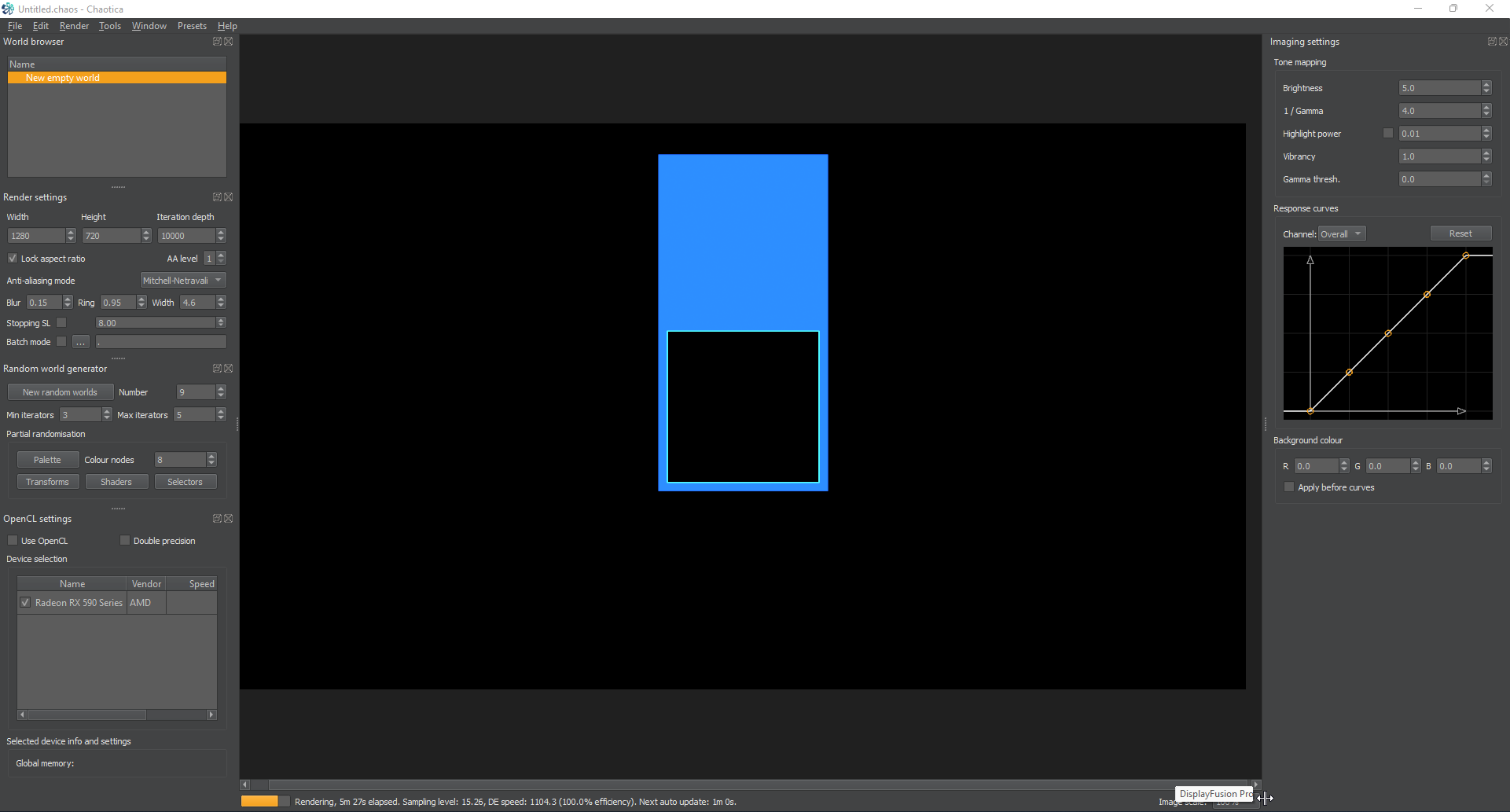
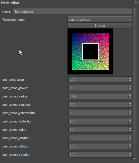
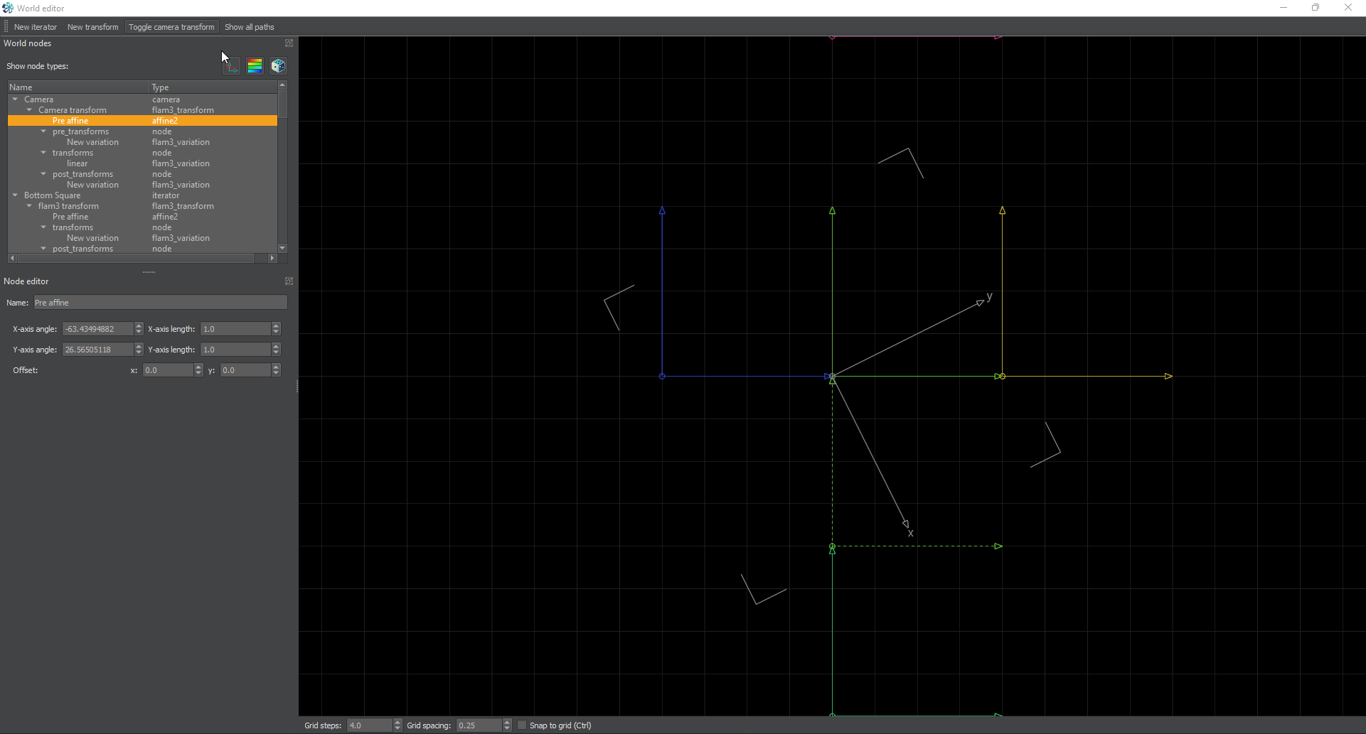
Now, I’m going to add a post-transform to the bottom square and I’ll make it a post-smartcrop. I’ll set the power on the post_smartcrop to -4. This will match the square but instead of cropping the outside, it will crop the inside due to the negative. Then I’ll drop the radius to 0.45 so it will leave a bit of a border.
Bottom Square Fill
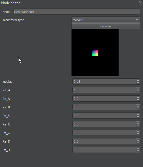
Now let’s fill it with something. First I’m going to create a new iterator. Next, I’ll set the transform to something neat. Hex_rand seems fun. It’s super large and overlaps, but we’ll take care of that. I’m going to then turn on the post-transform and toss in a mobius. That way I can adjust sizing, rotation and warping later if needed.
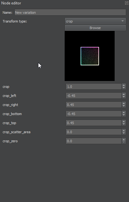
Next another post-transform of crop to crop out anything that goes over our size. This isn’t strictly needed if you perfectly control the size of the fill, but in this case I’m going to use it. I’m going to set the values on the crop to positive and negative 0.45 to match the other crop. Next I’m going to change the crop_scatter_area variable to 0 so it doesn’t put a ton of noise in there.
I’m going to list here the reasons I did it this way.
First off, the crop lets you swap out the hex rand for other things without having to worry about it overlapping later and having to go through the extra time of fiddling with it to make the overlap work. It just handles it.
Second, This shows you yet another way to play with tiles. You can get away with a lot by using post_smartcrop and other crops in both the pre and post transform. It illustrates the need to think of Chaotica as a different editor than others.
This is yet another example of the incredibly important chain methods that Chaotica is capable of. The ability to basically program an iterator using pre and post transform chains is incredibly mind blowing to me.
Lastly, I’m going to go back to the mobius and change its size down some so I can have more of the hexes inside the crop area. I could do all kinds of things with the mobius and that might be a good area to play with later.
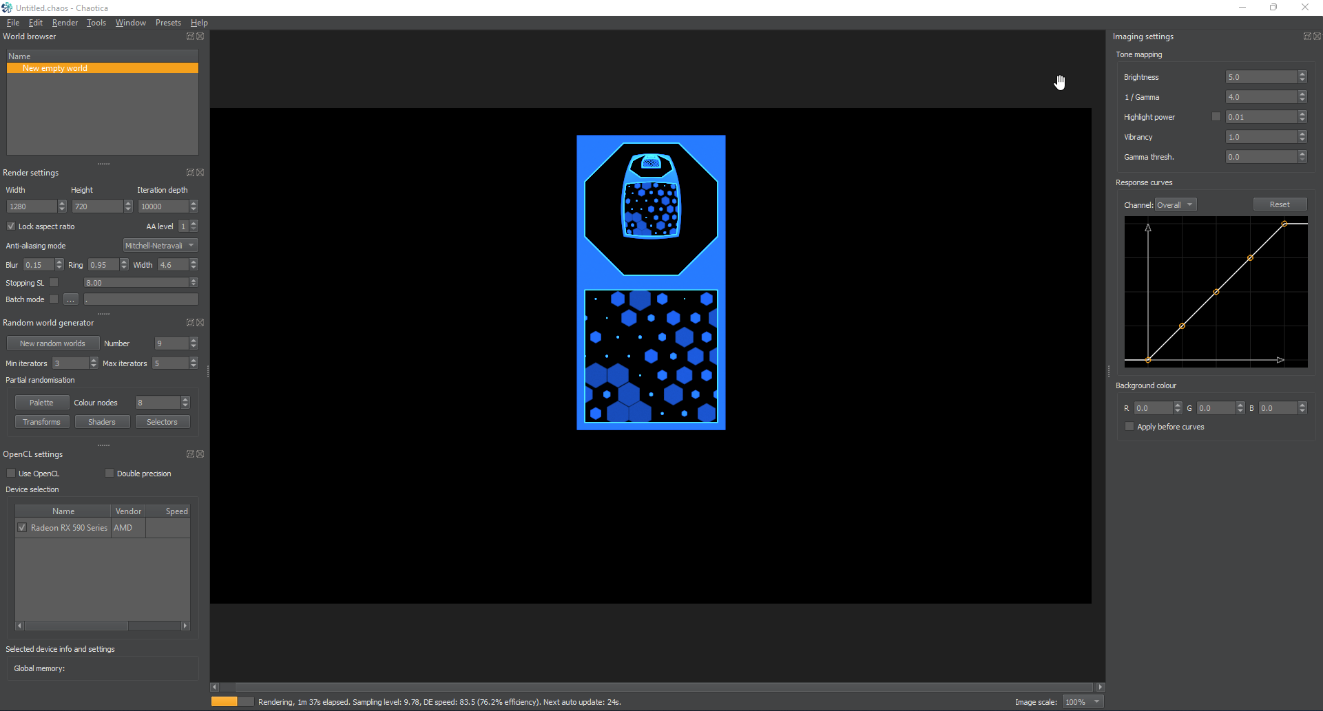
Sorry for the wall of text. Here’s what I ended up with.
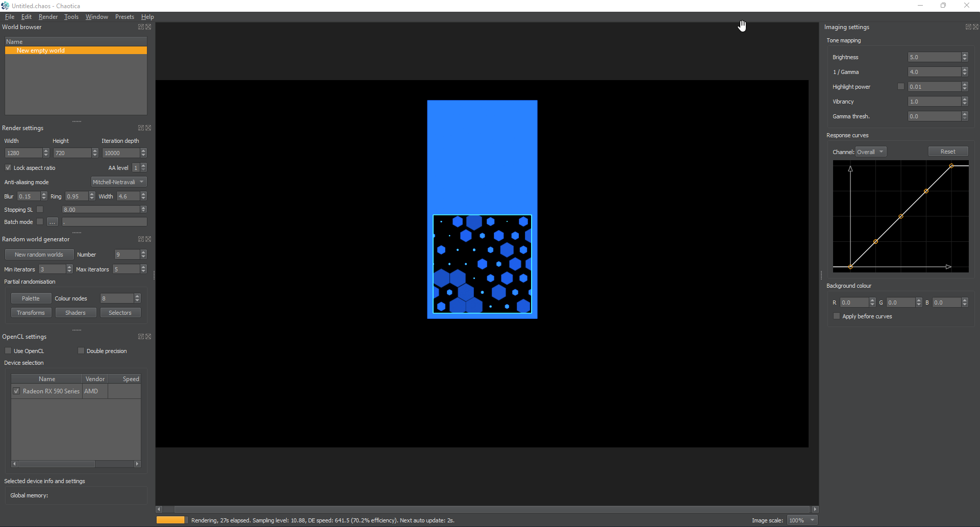
Top Square Fill
Now let’s do something entirely different for the second one. I’m thinking something exotic like an octogon cut-out with a sphere inside it.
First, I’m going to go back to that top square iterator (glad I named it) and add in a post smartcrop. This time with a power of -8 for the octogon cutout and a radius of 0.45
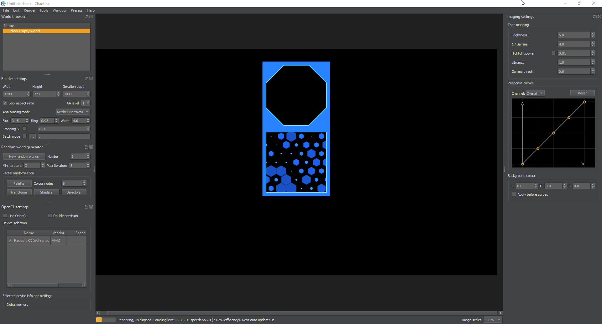
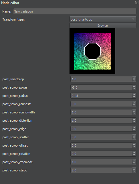
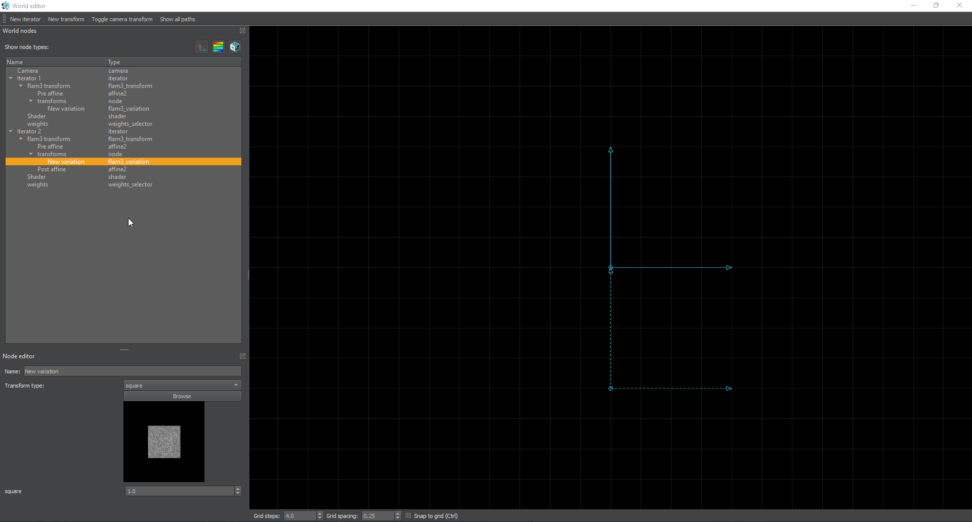
Next I’m going to create a new iterator, and shift the post-affine up to match the top square it’s supposed to fill. That means the post-affine will be set to -1.0 on the y axis. I’m going to set the transform to hemisphere so we can get a good coverage and have a pseudo-3d effect.
Lastly, I’m going to create a post-transform of mobius and set its size to 0.45 to match the crop.

Setting Up the Tiled Plane
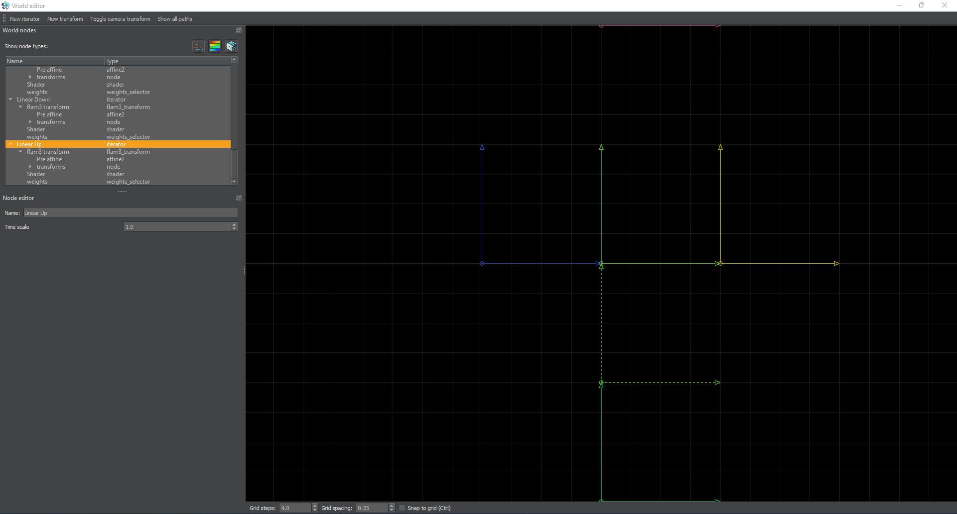
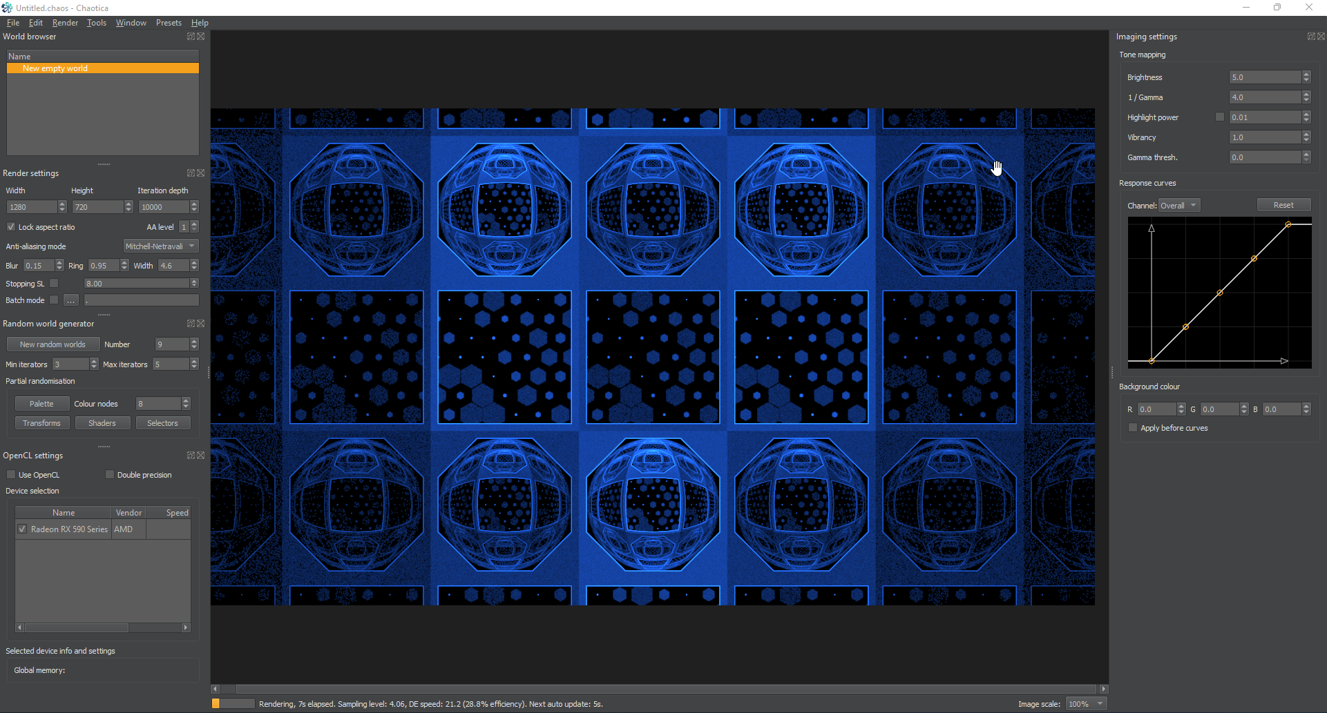
Now is a great time to see how this is going to look when it’s tiled. I’m going to create four more iterators, set them all to have a transform of linear, and then set the pre-affine to each linear direction. (If you’ve been through my previous linear tutorial, this will be familiar to you. If not, one of the iterators gets the coordinates (1,0) and the next gets (-1,0) and then the next two get (0,2) and the last (0,-2). It’s just moving things around so it tiles.) For the y values instead of +/-1 they are going to be +/-2 because this is taller than standard.
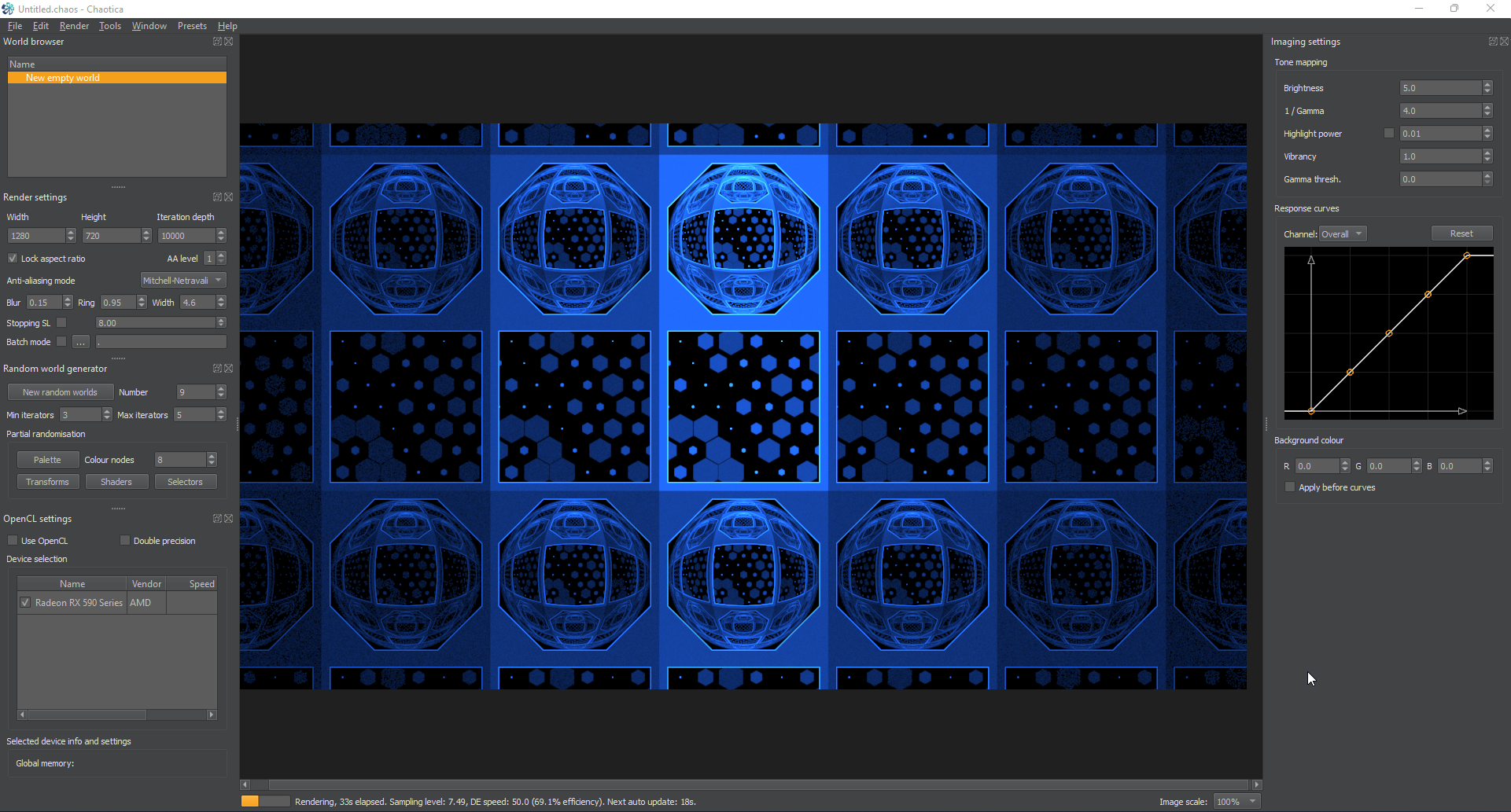
Here’s what it looks like after creating them.
Weights and Coloring
Now that we have something to work with, let’s do a bit of housekeeping. This is a great time to make sure everything is named so that when you go play with weights it’s all labelled right. That’s right, naming an iterator changes the name in the weights node to match. It’s super handy when you get into more advanced things.
To start with. all of the blurs can have their opacity turned to 0. Let me interject with a little knowledge here so newbies will know what I’m talking about.
Types of Transforms
There are three main types of transform. Keep in mind that this is my own interpretation and others may see it differently.
Blurs
Blurs are transforms that distribute points. If you’ve been through my previous tutorials, you may have seen the link I posted, or even watched the video on the chaos game. That’s basically what blurs are. They distribute points, which get displayed as “solid” color by the software. Examples of blurs are square, hex_rand, circleblur, gaussian_blur etc…
Modifiers
Modifiers are transforms that act as rules. They take the points distributed by blurs and then change or translate them in some way according to the rules they contain. An example of this is bipolar or hemisphere.
Hybrids
These both distribute points and tranform or translate. There are some transforms that do both. They can distribute points, or they can modify other points, or they can do both at the same time. I’ll leave these to you to discover. It gives you a reason to learn what they all do and how they interact.
Back on topic.
Now after going into all the shader nodes and setting the opacity on everything except the linears to 0, you’ll notice that the bright spots in the middle are a lot less pronounced. We don’t need those to be visible as the linears are picking up the points and providing full coverage. Here’s what it looks like.
We still have a bit of a bright spot in the middle because of the weights on the linears. Let’s adjust that now so it looks more uniform.
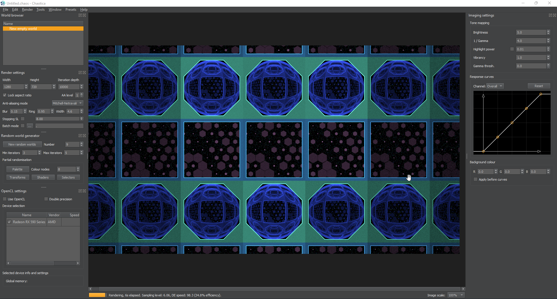
I’m going to look at the weights on the linears and set their base weight to somewhere in the realm of 4. This is a little brighter and more filled out. You can edit this however you like(I suggest doing so until you’re happy), and you’ll notice that when you change the base weight on one of the linears, it lights up the section that the particular iterator controls more than the others. You can use this to control the coloring or “lighting” later on.
Next, I’m going to go back to the shader nodes and set this up for direct coloring. I want to control the color of each section and take the blending off. That way It all looks uniform. You might like to leave the blending, or you might like to mash the random shader button. That’s fine and do whatever makes you happy. However, in this example, I’m showing how to directly color an entire linear tile so please bear with me.
I’m going to set it up like this. I’m going to change the blending in all the linears to 0 and all the blurs to 1. When coloring, a blend value of 0 means full blending, and 1 means no blending. At least that’s a simple explanation for it. I want the linears to carry the form but not control the color, so I’m going to set it up like that.
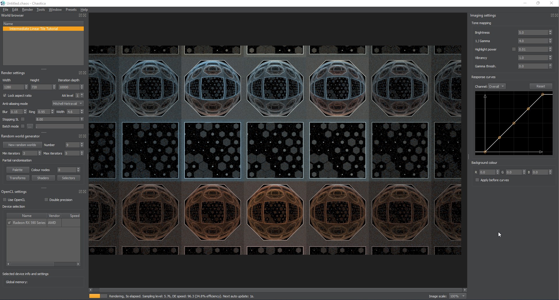
Next I’m going to go into the shader nodes on the blurs and play around with their palette location value. This will change all the blurs and fills together as you adjust. Here’s what mine looks like.
Now, this isn’t anywhere near what I would do in a full render. This is to show you how coloring works. Now that you’ve seen it, feel free to mash the shader button and see if you can make something cool. I’m going to inject some color in mine and then move on to the next section where I’ll show you how foci and unpolar work. They are the most popular camera modifiers for a linear tile.
Deep Dive into Foci and Unpolar
Next, let’s get you an idea of how unpolar and foci work. These are interesting. The best example I’ve seen comes from Pillemaster.
Imagine taking the 2d plane you have and wrapping it into a cylinder like wrapping paper and stare down the inside at the pattern. That’s unpolar. Now imagine taking that cylinder with the pattern on the inside and wrap it into a U shape where your view is inside the U bend and you’re looking down both lengths of it at the same time. That’s foci.
Now back to the practical. Using them. For the last part, I’m going to adjust the camera sensor width to around 3 to get the best views. Like always, adjust as you like.
Unpolar
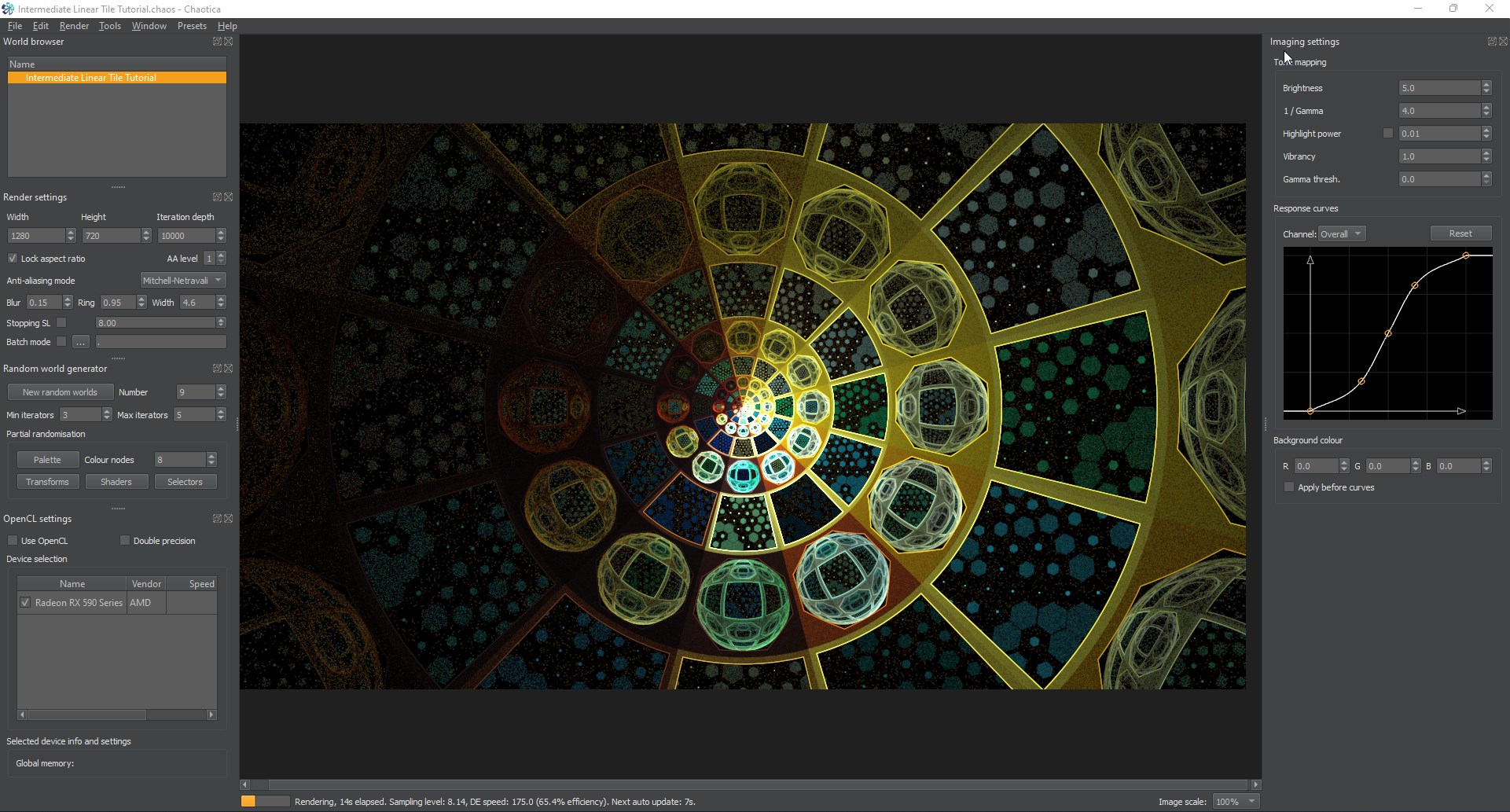
Unpolar is simple. You set it on the camera or an iterator like any other transform, but the key is that the size of whatever goes into it has to be a variant of pi/3. Using it is simple. Toggle your camera transform, and leave the linear there. Then create a post-transform and set it to unpolar. Looks blurry or overlapping right? Now…whip out your calculator and punch in pi/3. I’ll save you some time. The answer comes out to 1.047197551196. Set the value of the linear to that and watch the magic happen.
Now you may notice that even though it’s lined up right, it’s still…a little boring. Let’s divide the linear value by 2. To do this, i’m going to create a pre-transform on the camera and set it to linear. Set it to 0.5, which is half. After you set that, and it’s definitely looking a bit more interesting. Next, I’m going to adjust the coloring some more to compensate for the added complexity.
Foci
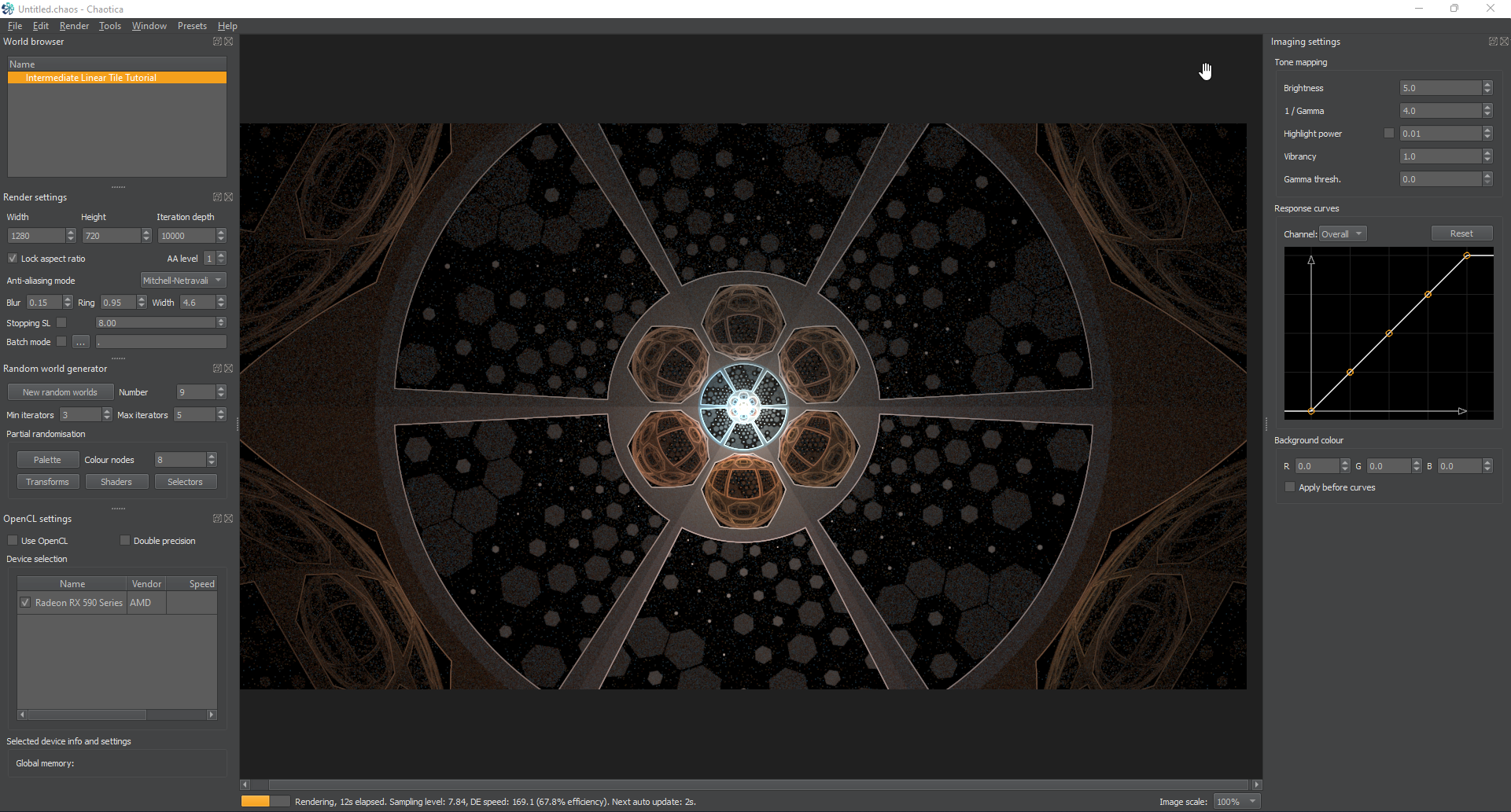
Next, foci is a bit more complex. When you’re using a basic foci, you can use the same sizing as the unpolar. You have to send whatever into it using a variation of pi/3. If i change the unpolar on the camera to foci, it looks like this.
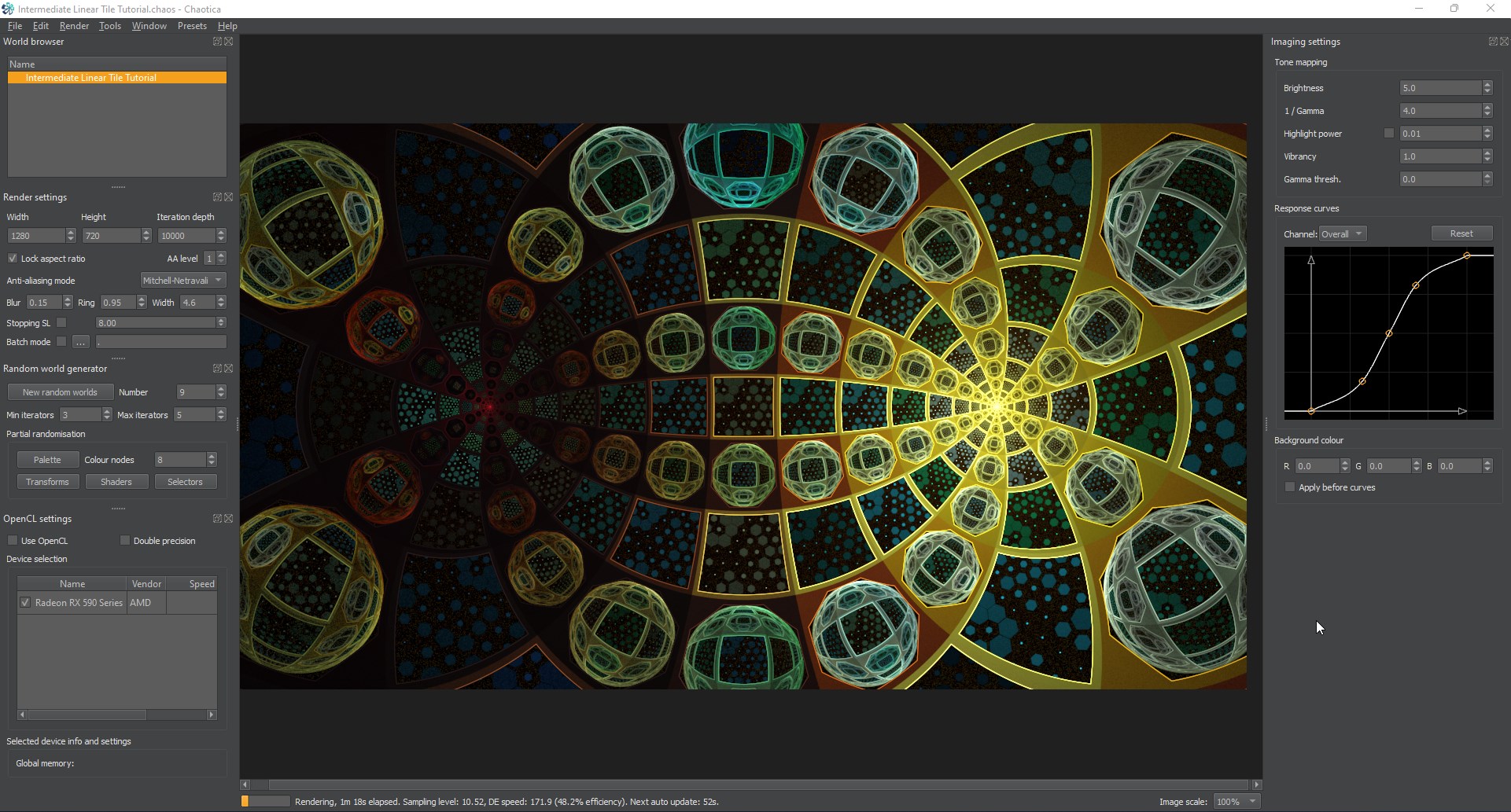
Looks pretty awesome right? Well, it can look even better.
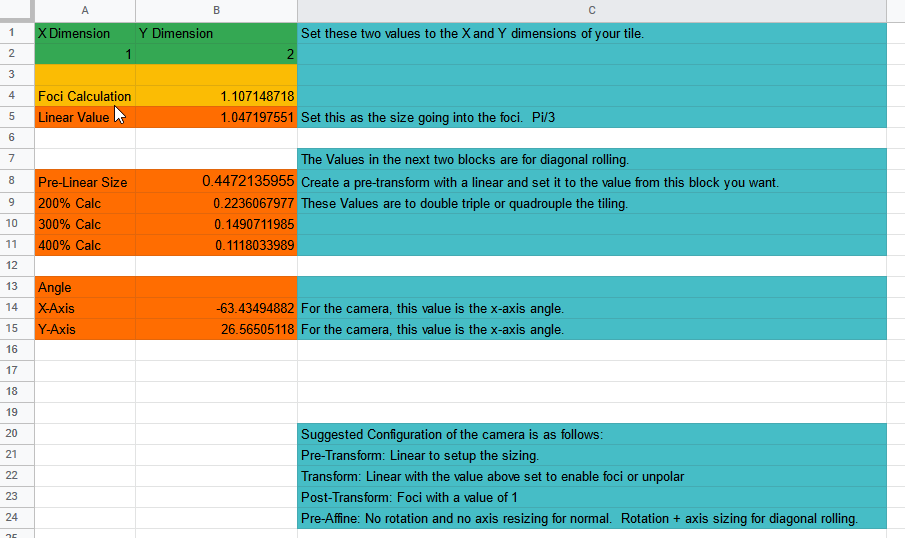
Now…let’s apply a diagonal roll to this. It’s basically turning it 45 degrees(Based on the sizing) and then adjusting it so it overlaps perfectly. If you’re interested, feel free to dig into the math. I suggest Pillemaster’s Tutorial as it’s incredibly detailed. I’m going to provide a calculator I wrote here for your use. This is specifically tailored to figuring out foci diagonal rolling in chaotica.
If I plug the values of the x and y tile into this, it gives me the values to set the linear, the pre-affine and the angles to make it overlap perfectly.
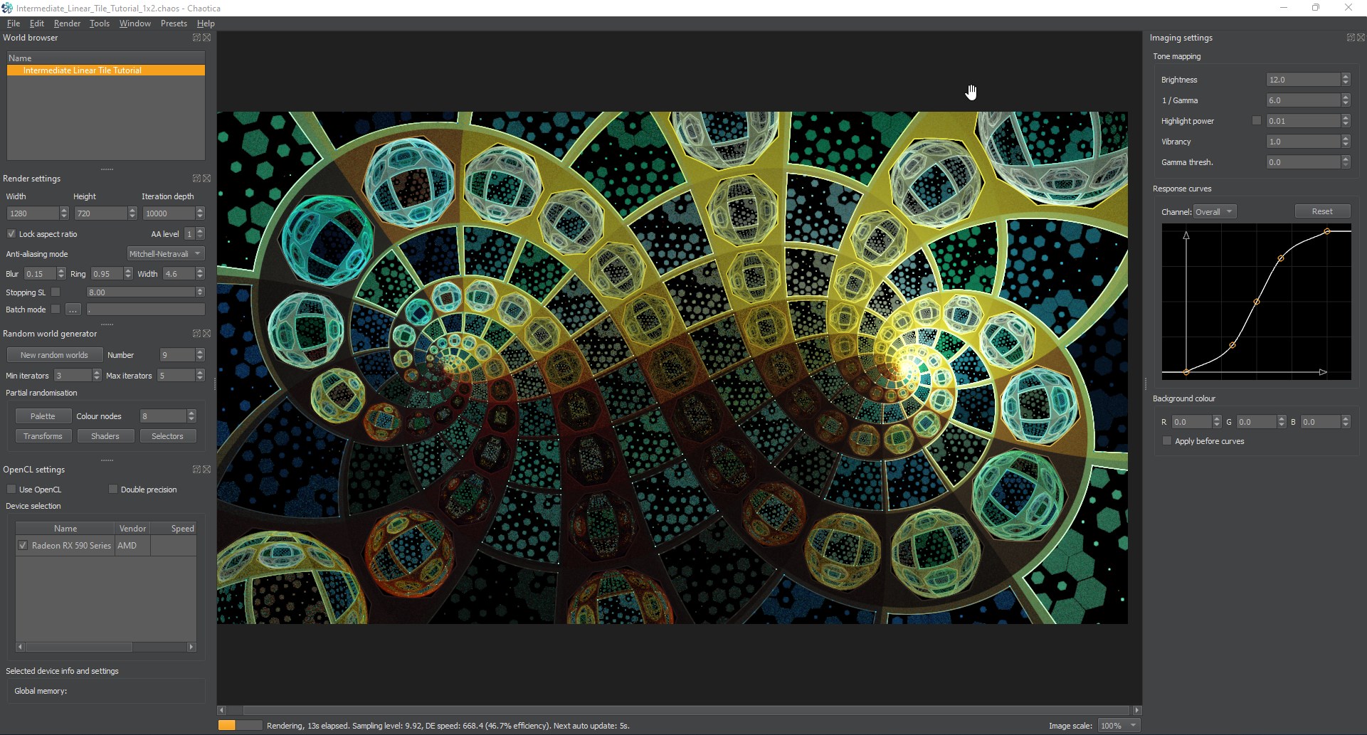
This is a 1x2 tile, so when I plug in those values, this is what I get.
And this is what it looks like with the following values on the pre-affine.
Finishing up
Now, keep in mind that I may be totally wrong on the math on this one. If I’m wrong, correct me. I’d love to make my calculator better and share it with everyone.
That being said, there are many ways to do this. You can tile it as far as your imagination can take you and beyond. Keep playing with the variables and before you know it, I’ll be learning from you. That’s the hope anyway.
One variable you can use is send the foci on the camera to e-julia. It turns it from what you just saw, to this.
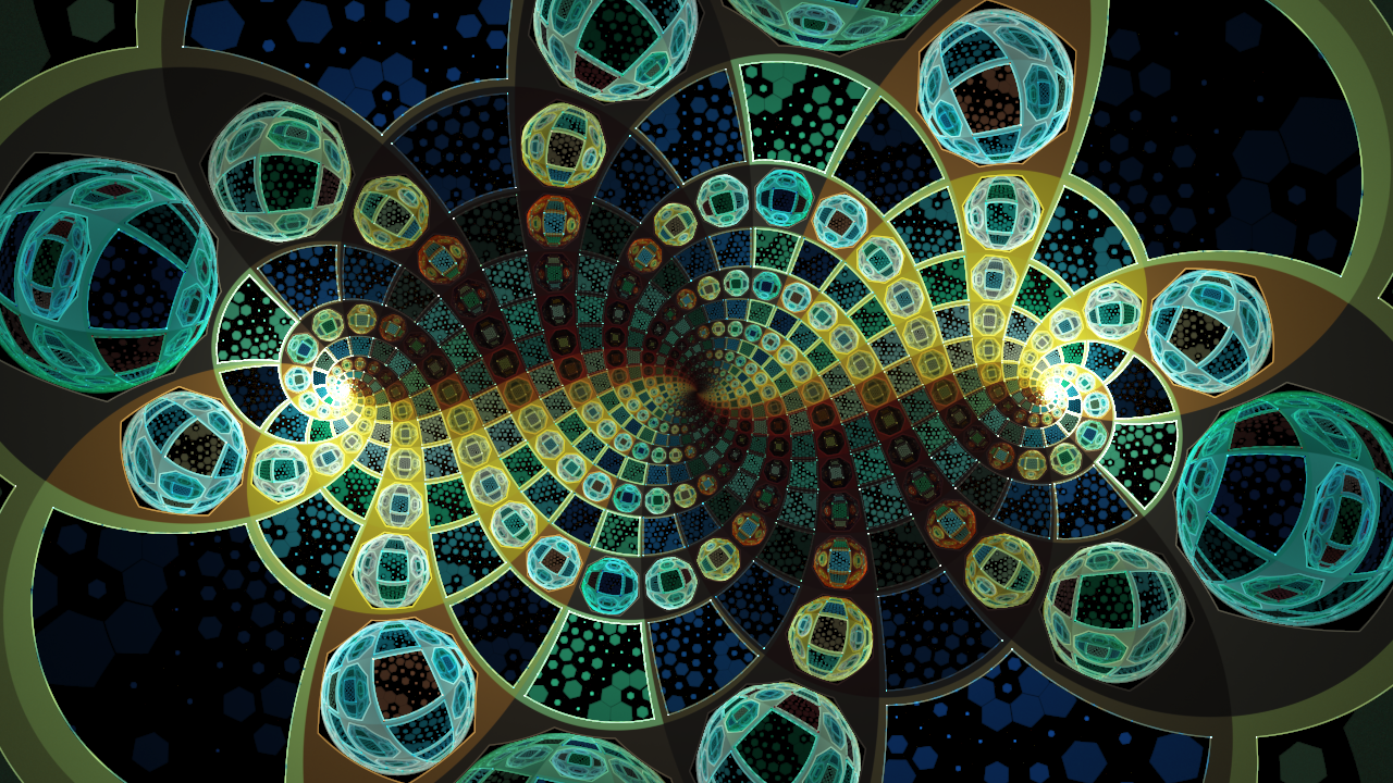
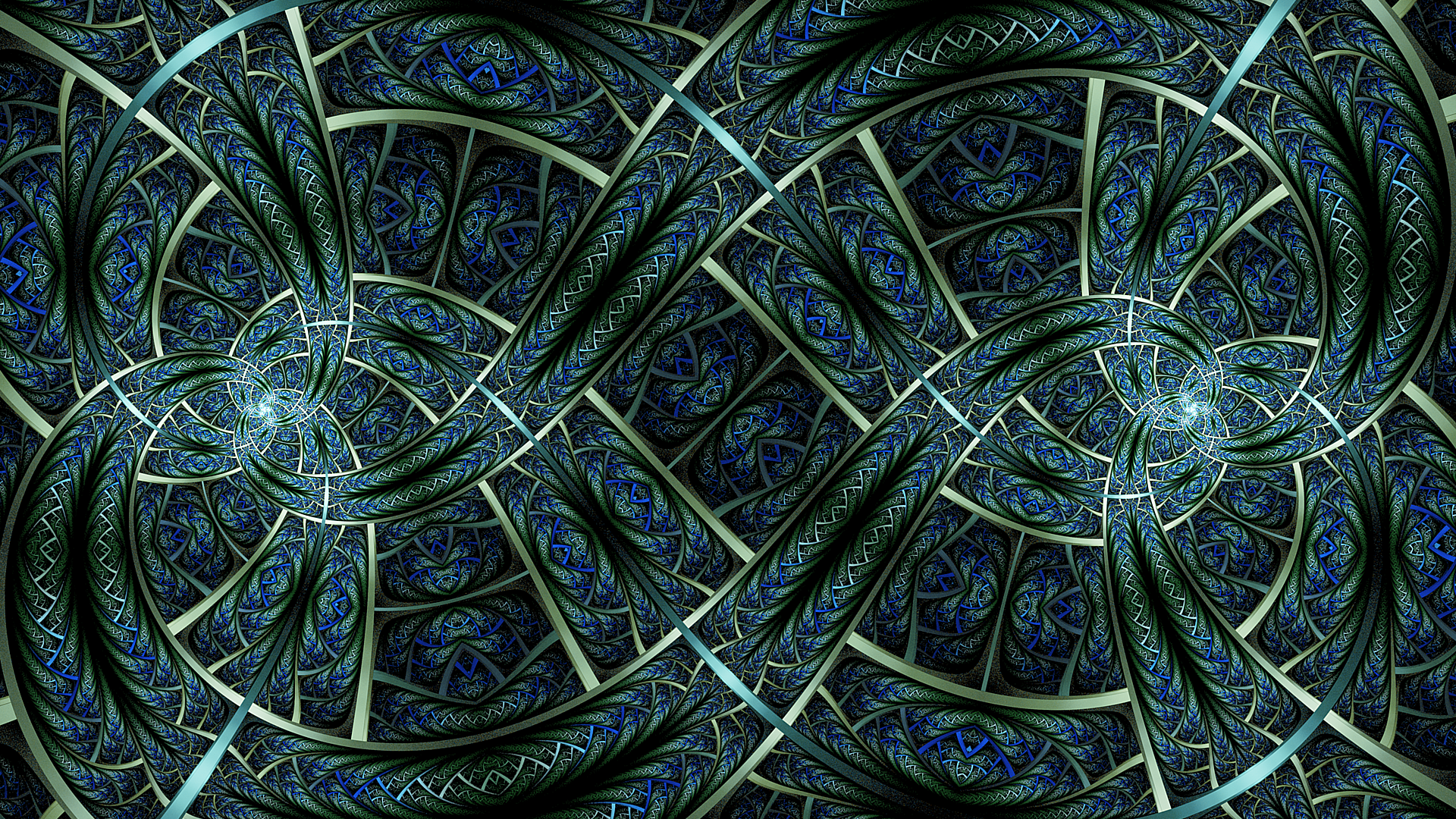
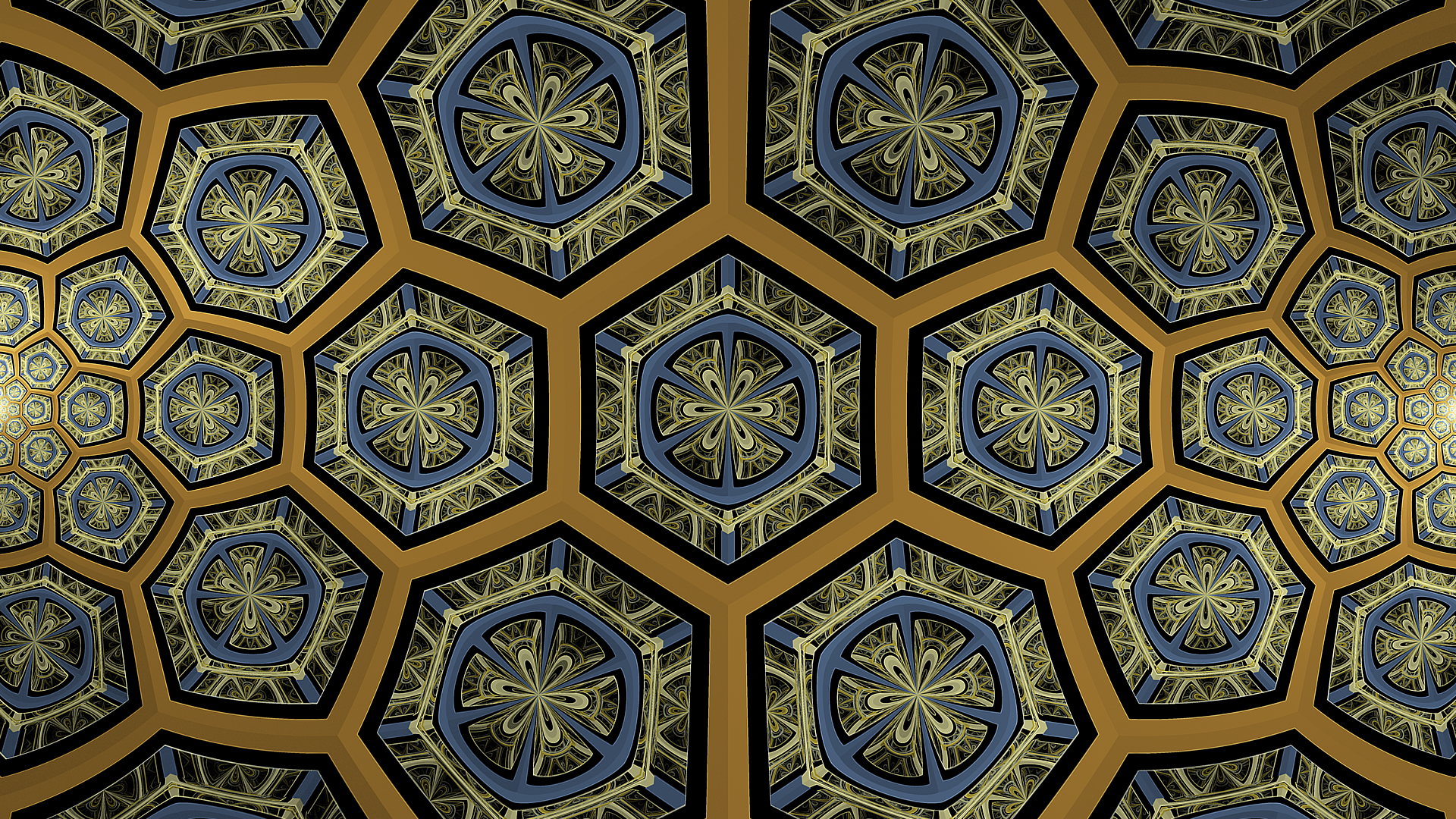
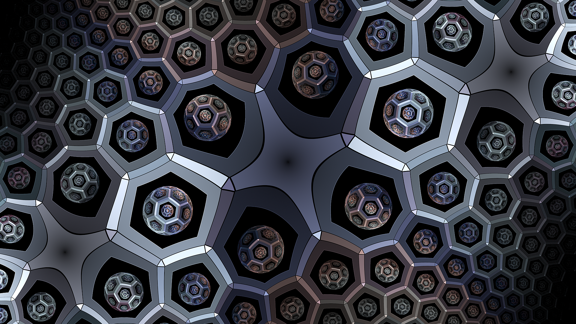
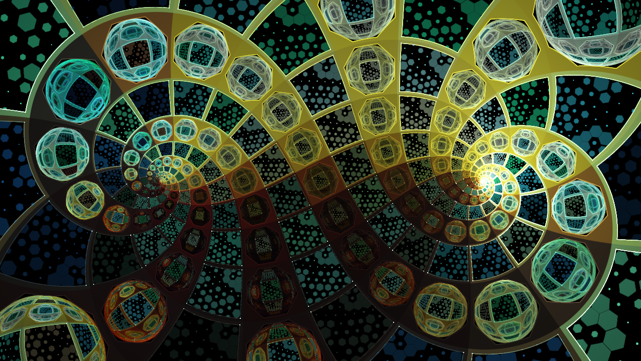
Examples
At this point though, where you take the fractal is up to you. I’ll leave you with a few examples of what I have created with this method.